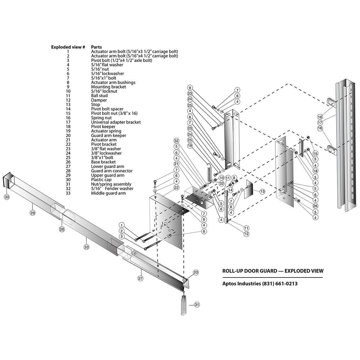
NOTE: In most applications the Roll-Up Door Guard (RUDG) is mounted on the side opposite the chain hoist, approximately 4 feet off the ground, depending on door height (see step 5). These instructions are written for a 14’ high door. The RUDG is shipped to mount on the left side of the door (Figures 1-7). Field conversion to right hand mount is easily accomplished. The exploded view shows a right-hand mount configuration for reference.
Step 1
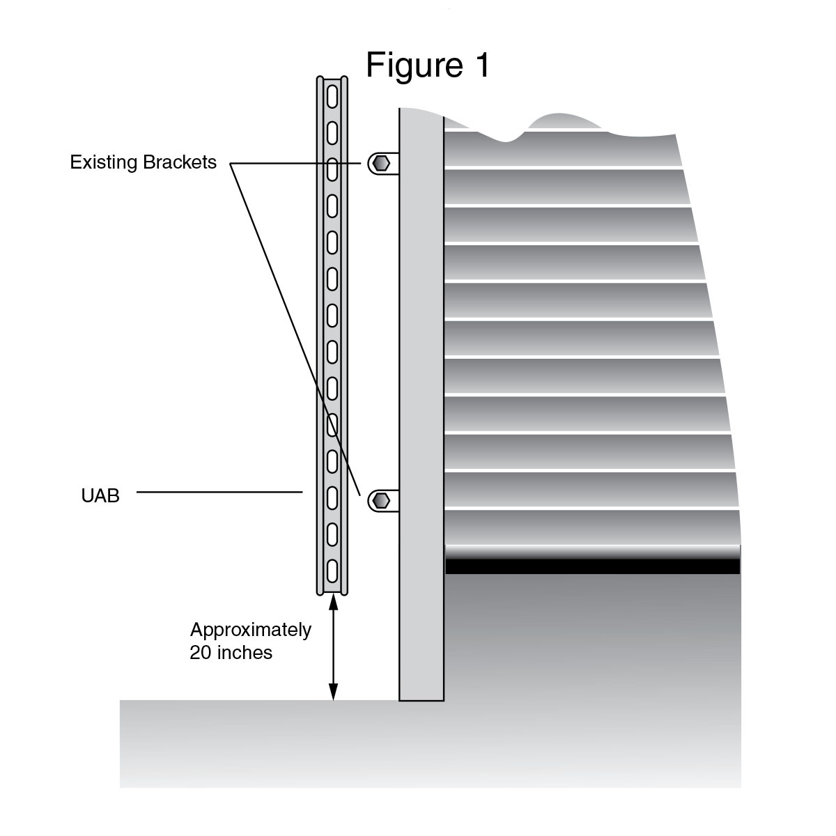
Place the Universal Adapter Bracket (UAB) (I7) approximately where the RUDG is to be mounted. The bottom of the UAB should be about 20 inches from the floor. Locate the existing door mounting bolts that fall within the span of the UAB. Remove the nuts/bolts from the existing mounting and place the UAB over the holes/studs. Replace the nuts/bolts to secure the UAB to the wall/frame of the overhead door. Figure 1
Alternative mounting method for steel frame buildings shown in Figures 8 & 9 thumbnails below (click to enlarge).
Step 2
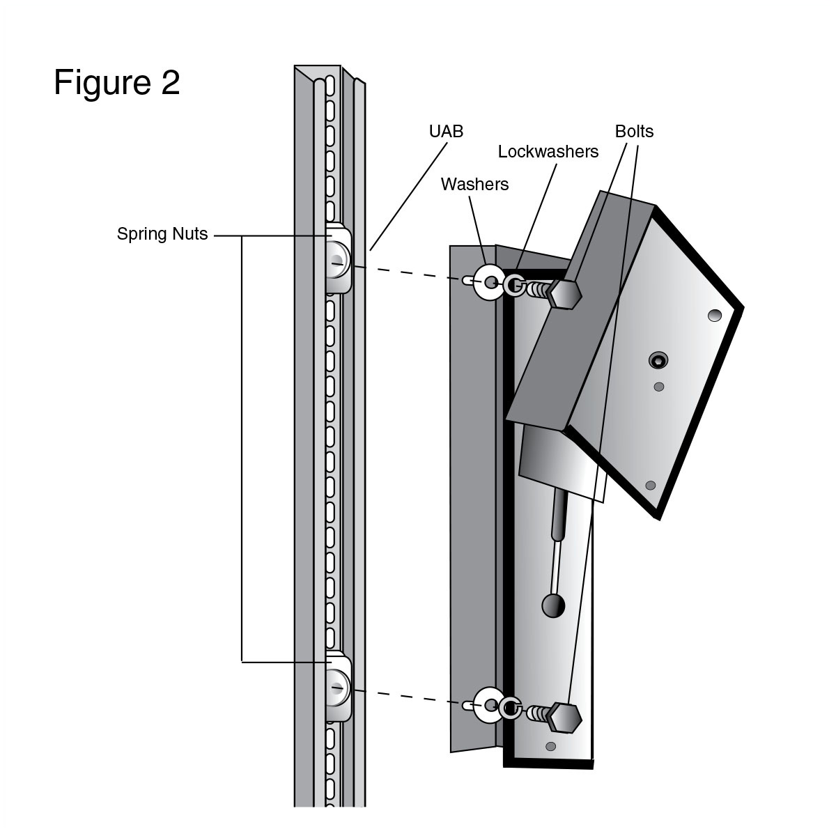
Insert two spring nuts (16) into the UAB. Position the bottom nut 34 inches from the floor. Position the top nut 48 inches from the floor. Using two 3/8x 1″ bolts (with lock washer and flat washer) (25,24,23) attach the RUDG to the UAB. Hand tighten the bolts. Figure 2
Step 3
Slide the lower guard arm (27) into position on the pivot bracket (22) so that the holes align. Place the guard arm retainer bracket (20) inside the lower guard arm and attach with two 5/16x 1” bolts (with lock washer and flat washer) (7,6,4). Thread nut/spring assembly onto exposed threads of rear-guard arm bracket. Figure 3
Step 4
Insert the guard arm coupling (28) into the free end of the lower guard arm (27) by compressing the coupling to fit inside the lower guard arm. Push the coupling into the lower guard arm until the alignment marker just disappears inside the lower guard arm. Attach the upper guard arm (29) to the lower guard arm by compressing the free end of the guard arm coupling and sliding the upper guard arm over the coupling until the upper and lower guard arm sections meet. Figure 4. Install black cap on free end of guard arm.
Step 5
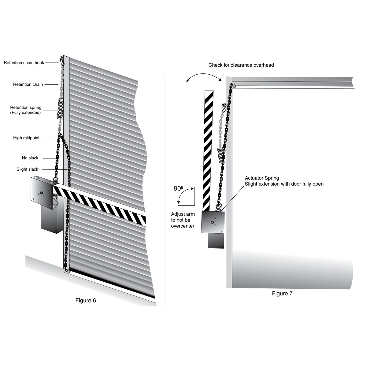
Rotate the assembled guard arm to the open (vertical) position to check that nothing interferes with the operation of the guard arm. Adjust RUDG so that the guard arm does not go over center in fully open position. Figure 7. Lower the height of the RUDG on the UAB if necessary to clear any overhead obstacles. Tighten the bolts (25) on the UAB. Return the guard arm to closed (near horizontal) position.
Step 6
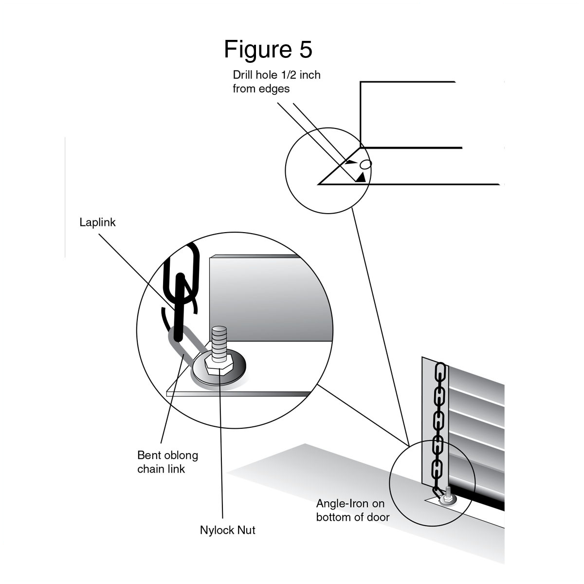
Position the bottom edge of the overhead door at about waist height. The next step will be to attach the actuator chain to the trailing edge of the door. The chain is bolted to the keeper on the bottom of the door. Figure 5 (On sectional door without bottom keeper, the chain can be bolted to bottom handle)
Step 7
Drill a 1/4″ hole into the keeper, 1/2” from each side. Attach the bent oblong chain link to the keeper using a 1/4x 1” bolt. The bolt must be installed upside down. Secure with 1/4″ locknut and washer. Attach one end of actuator chain with a laplink and close laplink. Figure 5
Step 8
Raise the overhead door to the fully open position, allowing the attached chain to hang freely. Raise the guard arm to the open (vertical) position. Using a laplink, attach the free end of the actuator spring (the spring attached to the RUDG) to the nearest link of the chain hanging from the door. Do not close laplink. Slightly lower door and move laplink up two links of the actuator chain. Re-open door. Check spring for slight extension in fully open position. Continue moving laplink up actuator chain one or two links at a time until correct adjustment is obtained. Close laplink. Cut off excess chain or, using ties provided, secure excess chain to itself.
Step 9
Grasp chain approximately 2 feet above the RUDG. Lower door to fully closed position and lower guard arm to closed position (near horizontal). Determine the high midpoint of chain and attach laplink to this point. Attach spring end of retention chain to laplink and close laplink. Figure 6
Step 10
Determine length of retention chain by finding attachment point on existing door mounting hardware between 3 and 4 feet from high midpoint. Attach closed loop end of retention chain hook to door frame using existing nut/bolt. Pull retention chain up until slack spring is fully extended. Attach the free end of retention chain to the open loop end of the retention chain hook. Figure 6. Open the door to check operation of door guard and adjust chain if necessary. Figure 7